VHDL | Total VHDL introduction and codes | vhdl tutorial
VHDL
Introduction:
VHdl is a hardware description language (HDL) that can model the behavior and structure of
digital systems at multiple levels of abstraction, ranging from the system level down to that of logic gates,
for design entry, documentation, and verification purposes.
What does vhdl stand for?
VHDL stands for very high-speed integrated circuit hardware description language.
It is a programming language used to model a digital system by dataflow, behavioral and
structural style of modeling. This language was first introduced in 1981 for the Department
of Defense (DoD) under the VHSIC program.
Application of vhdl:
i) CPLD: Complex programmable logic device
ii) ASIC: Application Specific Integrated Circuit .
iii) FPGA: Field Programmable Gate Arrays.
It should be taken into consideration that once the VHDL code has been written it can be
used to implement. The circuit is a programmable device.
Why is VHDL referred to as code ?
Because it is not sequential rather than concurrent or parallel one of the major utilities of
VHDL is that it allows one synthesis of circuit or system in a programmable manner.
Fundamentals of VHDL unit:
i) Library
ii) declaration,
iii)Entity
iv) Architecture.
v) Basic VHDL code.
1.Library:
Library contains a collection of commonly used pieces of VHDL code. Usually in the
Library, codes are written in the form of Function, Procedure and Packages
(these are discussed later). Main part of VHDL code is the Library declaration.
contains a list of libraries to be used for the design- ieee, std, Work etc.
Read: Mother's Fringe (calling of death by corona virus)
2.Entity:
Entity is the list of input and output ports. It is a library unit which describes the
external interface of a hardware module.
3.Architecture
A library unit associated with an entity which describes its internal operation or
organization. Multiple architectures may be defined for a single entity.
How to declare a library ?
A library is a commonly Used piece of Code. Placing Such Pieces inside a library
allows them to be used or share the designs.
To declare a library two lines of code needed, one Containing the name of the library
and the other use a facility as shown below:-
LIBRARY Library_name;
USE Library_name.Package_name.Package_Parts;
At least 3 Packages from different library as needed -
(1) ieee std_logic_1164 (from ieee)
(2) Standard (from the std library)
(3) Work (work library)
The declaration will look as follows:
library IEEE;
use IEEE. STD-LOGIC _1164. ALL;
use IEEE. STD-LOGIC _ ARITH. ALL;
use IEEE. STD.LOGIC_UNSIGNED. ALL;
use work. All;
Xilinx programs with output:
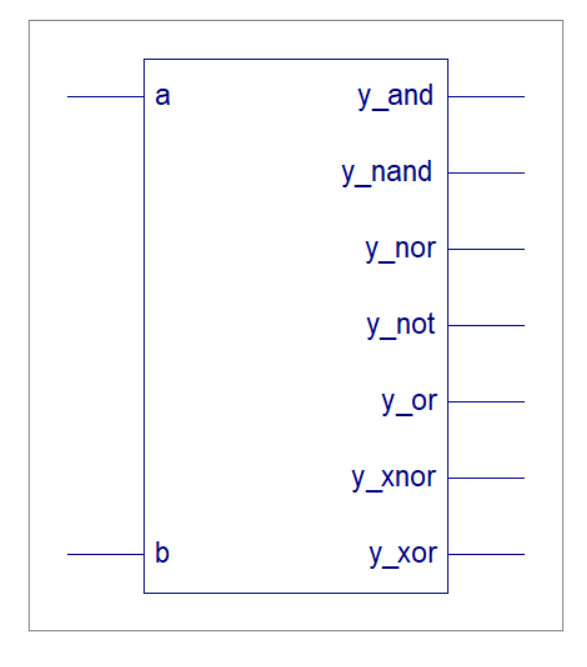
All gates(and,or,nand…) in one code. The code is as follows:
library IEEE;
use IEEE.STD_LOGIC_1164.ALL;
use IEEE.STD_LOGIC_ARITH.ALL;
use IEEE.STD_LOGIC_UNSIGNED.ALL;
---- Uncomment the following library declaration if instantiating
---- any Xilinx primitives in this code.
--library UNISIM;
--use UNISIM.VComponents.all;
entity new1m is
Port ( a,b : in STD_LOGIC;
y_and,y_or , y_nand, y_nor, y_not, y_xor ,y_xnor: out std_logic);
end new1m;
architecture Behavioral of new1m is
begin
y_and <= a and b;
y_or <= a or b;
y_nand <= a nand b;
y_nor <= a nor b;
y_not <= not a;
y_xor <= a xor b;
y_xnor <= a xnor b;
end Behavioral;
Output :
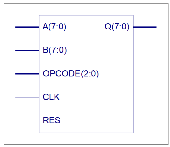
8 bit register .The code is as follows:
library IEEE;
use IEEE.STD_LOGIC_1164.ALL;
use IEEE.STD_LOGIC_ARITH.ALL;
use IEEE.STD_LOGIC_UNSIGNED.ALL;
---- Uncomment the following library declaration if instantiating
---- any Xilinx primitives in this code.
--library UNISIM;
--use UNISIM.VComponents.all;
entity 8bitregister is
Port ( CLK : in STD_LOGIC;
RES : in STD_LOGIC;
OPCODE : in STD_LOGIC_vector(2 downto 0);
A : in STD_LOGIC_vector(7 downto 0);
B : in STD_LOGIC_vector(7 downto 0);
Q : out STD_LOGIC_vector (7 downto 0)
);
end 8bitregister;
architecture Behavioral of 8 bit register is
begin
process(clk)
begin
if rising_edge(clk) then
if RES = '1' then
Q <= (others => '0');
else
case OPCODE is
when "000" =>
Q <= not(A);
when "001" =>
Q <= not(A xor B);
when "010" =>
Q <= not(A or B);
when "011" =>
Q <= not(A and B);
when "100" =>
Q <= A;
when "101" =>
Q <= (A xor B);
when "110" =>
Q <= (A or B);
when "111" =>
Q <= (A and B);
when others =>
Q <= (others => '0');
end case;
end if;
end if;
end process;
end Behavioral;
Output:
Read: Best Meaningful Illustration Picture about Life
3) 8 bit simple ALU design. The code is as follows:
library IEEE;
use IEEE.STD_LOGIC_1164.ALL;
use IEEE.STD_LOGIC_ARITH.ALL;
use IEEE.STD_LOGIC_UNSIGNED.ALL;
---- Uncomment the following library declaration if instantiating
---- any Xilinx primitives in this code.
--library UNISIM;
--use UNISIM.VComponents.all;
entity ALU is
Port ( A,B : in STD_LOGIC_VECTOR (7 downto 0);
ALU_Sel : in STD_LOGIC_VECTOR (2 downto 0);
NZVC : out STD_LOGIC_VECTOR (3 downto 0);
Result : out STD_LOGIC_VECTOR (7 downto 0));
end ALU;
architecture Behavioral of ALU is
signal ALU_Result:std_logic_vector(7 downto 0);
signal ALU_ADD: std_logic_vector(8 downto 0);
signal C,Z,V,N,add_ov,sub_ov: std_logic;
begin
process(ALU_Sel,A,B)
begin
ALU_ADD <= "000000000";
case(ALU_Sel) is
when "000" => -- ADD
ALU_ADD <= ('0' & A )+ ('0'& B);
ALU_Result <= A + B;
when "001" => -- SUB
ALU_Result <= B - A;
ALU_ADD <= ('0' & B) - ('0' & A);
when "010" => -- AND
ALU_Result <= A and B;
when "011" => -- OR
ALU_Result <= A or B;
when "100" => -- Increment
ALU_Result <= A + x"01";
when "101" => -- Decrement
ALU_Result <= A - x"01";
when others =>
ALU_Result <= A + B;
end case;
end process;
Result <= ALU_Result;
N <= ALU_Result(7);
Z <= '1' when ALU_Result = x"00" else
'0';
---Overflow flag---------------------------------------
add_ov<= (A(7)and B(7) and (not ALU_Result(7))) or ((not A(7))and (not B(7)) and
ALU_Result(7));
sub_ov<= (A(7)and (not B(7)) and (not ALU_Result(7))) or ((not A(7))and B(7) and
ALU_Result(7));
with ALU_Sel select
V <= add_ov when "000",
sub_ov when "001",
'0' when others;
---------Carry out flag
with ALU_Sel select
C <= ALU_ADD(8) when "000",
ALU_ADD(8) when "001",
'0' when others;
NZVC <= N & Z & V & C;
end Behavioral;
Output:

Read: Here are 9 ways to check fake or fake messages on WhatsApp.
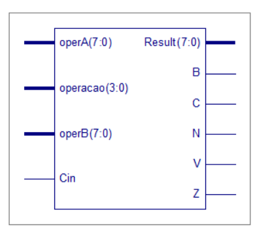
4. 8 bit simple CPU design. The code is as follows:
LIBRARY ieee ;
USE ieee.std_logic_1164.all ;
USE ieee.std_logic_unsigned.all ;
ENTITY ula IS
PORT
(
operacao : IN STD_LOGIC_VECTOR (3 DOWNTO 0);
operA : IN STD_LOGIC_VECTOR(7 DOWNTO 0);
operB : IN STD_LOGIC_VECTOR(7 DOWNTO 0);
Result : buffer STD_LOGIC_VECTOR(7 DOWNTO 0);
Cin : IN STD_LOGIC;
N,Z,C,B,V : buffer STD_LOGIC
);
END ula;
ARCHITECTURE ula1 OF ula IS
constant ADIC : STD_LOGIC_VECTOR(3 DOWNTO 0):="0001";
constant SUB : STD_LOGIC_VECTOR(3 DOWNTO 0):="0010";
constant OU : STD_LOGIC_VECTOR(3 DOWNTO 0):="0011";
constant E : STD_LOGIC_VECTOR(3 DOWNTO 0):="0100";
constant NAO : STD_LOGIC_VECTOR(3 DOWNTO 0):="0101";
constant DLE : STD_LOGIC_VECTOR(3 DOWNTO 0):="0110";
constant DLD : STD_LOGIC_VECTOR(3 DOWNTO 0):="0111";
constant DAE : STD_LOGIC_VECTOR(3 DOWNTO 0):="1000";
constant DAD : STD_LOGIC_VECTOR(3 DOWNTO 0):="1001";
BEGIN
process (operA, operB, operacao,result,Cin)
variable temp : STD_LOGIC_VECTOR(8 DOWNTO 0);
begin
case operacao is
when ADIC =>
temp := ('0'&operA) + ('0'&operB);
result <= temp(7 DOWNTO 0);
C <= temp(8);
if (operA(7)=operB(7)) then
if (operA(7) /= result(7)) then V <= '1'; else V <= '0';
end if;
else V <= '0';
end if;
when SUB =>
temp := ('0'&operA) - ('0'&operB);
result <= temp(7 DOWNTO 0);
B <= temp(8);
if (operA(7) /= operB(7)) then
if (operA(7) /= result(7)) then V <= '1'; else V <= '0';
end if;
else V <= '0';
end if;
when OU =>
result <= operA or operB;
when E =>
result <= operA and operB;
when NAO =>
result <= not operA;
when DLE =>
C <= operA(7);
result(7) <= operA(6);
result(6) <= operA(5);
result(5) <= operA(4);
result(4) <= operA(3);
result(3) <= operA(2);
result(2) <= operA(1);
result(1) <= operA(0);
result(0) <= Cin;
when DAE =>
C <= operA(7);
result(7) <= operA(6);
result(6) <= operA(5);
result(5) <= operA(4);
result(4) <= operA(3);
result(3) <= operA(2);
result(2) <= operA(1);
result(1) <= operA(0);
result(0) <= '0';
when DLD =>
C <= operA(0);
result(0) <= operA(1);
result(1) <= operA(2);
result(2) <= operA(3);
result(3) <= operA(4);
result(4) <= operA(5);
result(5) <= operA(6);
result(6) <= operA(7);
result(7) <= Cin;
when DAD =>
C <= operA(0);
result(0) <= operA(1);
result(1) <= operA(2);
result(2) <= operA(3);
result(3) <= operA(4);
result(4) <= operA(5);
result(5) <= operA(6);
result(6) <= operA(7);
result(7) <= '0';
when others =>
result <= "00000000";
Z <= '0';
N <= '0';
C <= '0';
V <= '0';
B <= '0';
end case;
if (result="00000000") then Z <= '1'; else Z <= '0';
end if;
N <= result(7);
end process;
END ula1;
Output:
5. Memory Unit Design.the code is as follows:
library IEEE;
use IEEE.STD_LOGIC_1164.ALL;
USE ieee.numeric_std.ALL;
---------A 128x8 single-port RAM in VHDL
entity Single_port_RAM_VHDL is
port(
RAM_ADDR: in std_logic_vector(6 downto 0); -- Address to write/read RAM
RAM_DATA_IN: in std_logic_vector(7 downto 0); -- Data to write into RAM
RAM_WR: in std_logic; -- Write enable
RAM_CLOCK: in std_logic; -- clock input for RAM
RAM_DATA_OUT: out std_logic_vector(7 downto 0) -- Data output of RAM
);
end Single_port_RAM_VHDL;
architecture Behavioral of Single_port_RAM_VHDL is
----------define the new type for the 128x8 RAM
type RAM_ARRAY is array (0 to 127 ) of std_logic_vector (7 downto 0);
-----------initial values in the RAM
signal RAM: RAM_ARRAY :=(
x"55",x"66",x"77",x"67",-- 0x00:
x"99",x"00",x"00",x"11",-- 0x04:
x"00",x"00",x"00",x"00",-- 0x08:
x"00",x"00",x"00",x"00",-- 0x0C:
x"00",x"00",x"00",x"00",-- 0x10:
x"00",x"00",x"00",x"00",-- 0x14:
x"00",x"00",x"00",x"00",-- 0x18:
x"00",x"00",x"00",x"00",-- 0x1C:
x"00",x"00",x"00",x"00",-- 0x20:
x"00",x"00",x"00",x"00",-- 0x24:
x"00",x"00",x"00",x"00",-- 0x28:
x"00",x"00",x"00",x"00",-- 0x2C:
x"00",x"00",x"00",x"00",-- 0x30:
x"00",x"00",x"00",x"00",-- 0x34:
x"00",x"00",x"00",x"00",-- 0x38:
x"00",x"00",x"00",x"00",-- 0x3C:
x"00",x"00",x"00",x"00",-- 0x40:
x"00",x"00",x"00",x"00",-- 0x44:
x"00",x"00",x"00",x"00",-- 0x48:
x"00",x"00",x"00",x"00",-- 0x4C:
x"00",x"00",x"00",x"00",-- 0x50:
x"00",x"00",x"00",x"00",-- 0x54:
x"00",x"00",x"00",x"00",-- 0x58:
x"00",x"00",x"00",x"00",-- 0x5C:
x"00",x"00",x"00",x"00",
x"00",x"00",x"00",x"00",
x"00",x"00",x"00",x"00",
x"00",x"00",x"00",x"00",
x"00",x"00",x"00",x"00",
x"00",x"00",x"00",x"00",
x"00",x"00",x"00",x"00",
x"00",x"00",x"00",x"00"
);
begin
process(RAM_CLOCK)
begin
if(rising_edge(RAM_CLOCK)) then
if(RAM_WR='1') then -- when write enable = 1,
-----------write input data into RAM at the provided address
RAM(to_integer(unsigned(RAM_ADDR))) <= RAM_DATA_IN;
-----------The index of the RAM array type needs to be integer so
-----------converts RAM_ADDR from std_logic_vector -> Unsigned -> Integer using
-- numeric_std library
end if;
end if;
end process;
-----------Data to be read out
RAM_DATA_OUT <= RAM(to_integer(unsigned(RAM_ADDR)));
end Behavioral;
Output:

To read more article :Nilranbow.blogspot.com